
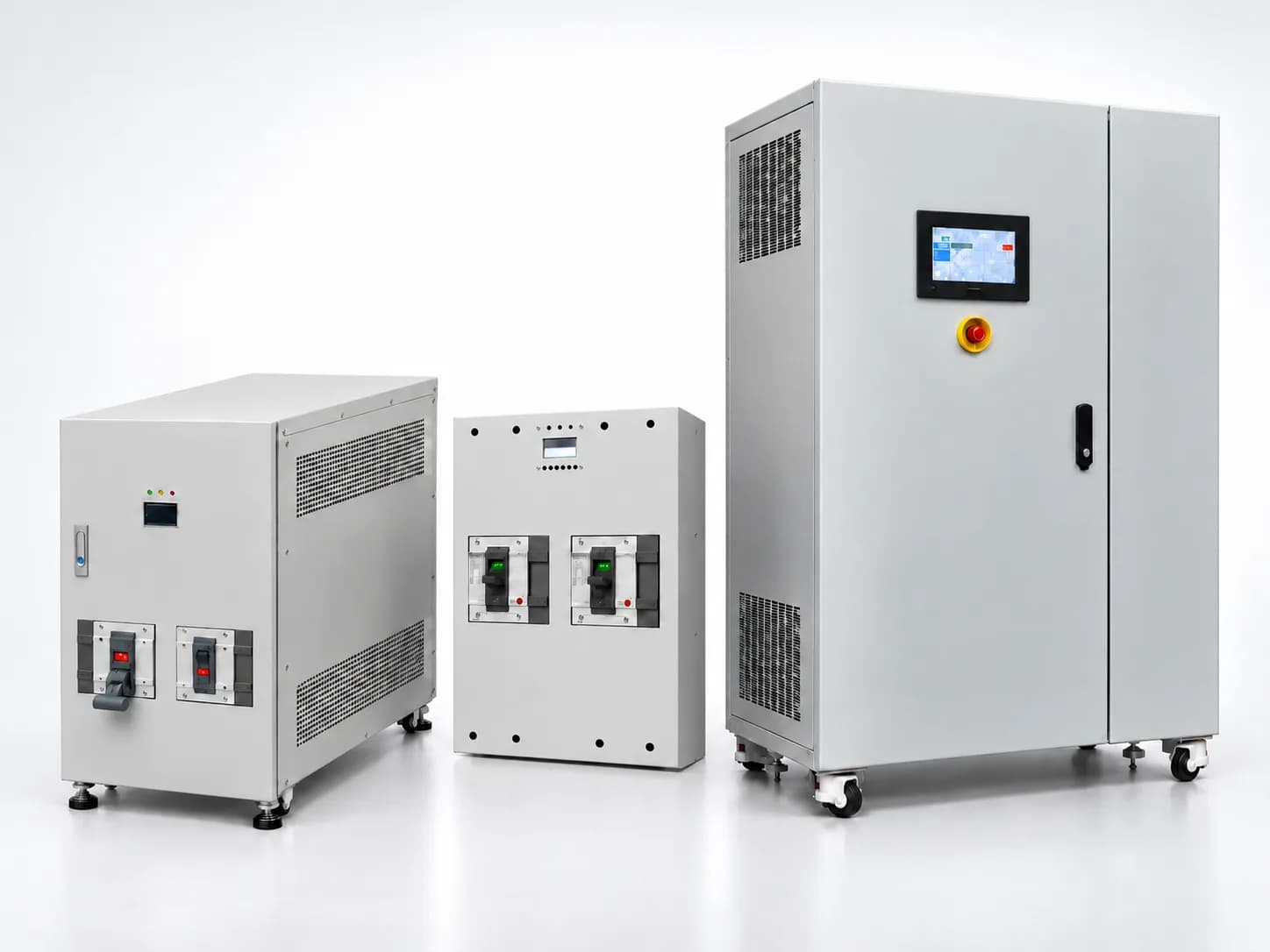
Product Description
The Sag Simulator receives two voltage inputs: a normal voltage and a sag voltage. It selectively delivers one of three output states—Normal, Sag, or Open—to simulate various voltage conditions.
The device allows users to configure operating conditions based on parameters such as phase, cycle, and time.
Its built-in overcurrent protection function instantly interrupts the output in the event of load overcurrent, preventing potential accidents and equipment damage.
When combined with an external variable autotransformer (Variac), transformer, or inverter-based power source, the Sag Simulator can be used to perform voltage sag immunity testing in accordance with the SEMI F47 standard.

Technical Specifications
Item | Specification | Remarks |
Rated Input Voltage | Single-phase / Three-phase 200V~480V | Internal control transformer wiring configuration required |
Variac (SL) Input Voltage | 0~510Vac | |
Input Frequency | 48~62Hz | |
Input/Output Current | Depends on rated capacity | |
Sag Duration | 1~2000Cycle(=16.7ms~16.7s) 1ms~20000ms(20s) | Cycle Mode Time Mode |
Cycle Duration | 1~2000Cycle(=16.7ms~16.7s) 1ms~20000ms(20s) | Cycle Mode Time Mode |
Display & Controls | 8x20 Character LCD 4 Push Button | |
Sync Pulse Output | Amplitude : 0~9V Polarity : Positive | Electrically Isolated Output |
Operating Temperature | Ambient Temperature 15℃~45℃ | |
Dimensions (W × D × H) | 550x400x200 (30kVA) 716x500x330 (50kVA) 716x500x500 (100kVA) 1050x500x860 (200kVA) 1000x600x1800 (400kVA) |
Sag Simulator Block Diagram

PC External Control Program

Sag Simulator 100kVA Picture

Control Parameter
No | Parameter | Value (Display) | Description | Remarks |
1 | Operating Mode | [Ang] | Angle Mode: Set the start and end phase angles |
|
[ms] | Time Mode: Set the start phase angle and duration |
| ||
2 | Output Voltage Mode | BYPASS | Maintain the rated (normal) voltage |
|
BYP>SAG | Switch from normal voltage to sag voltage |
| ||
BYP>OPN | Switch from normal voltage to open circuit |
| ||
SAG | Maintain the sag voltage |
| ||
SAG>BYP | Switch from sag voltage to normal voltage |
| ||
SAG>OPN | Switch from sag voltage to open circuit |
| ||
OPEN | Maintain the open-circuit state |
| ||
OPN>BYP | Switch from open circuit to normal voltage |
| ||
OPN>SAG | Switch from open circuit to sag voltage |
| ||
3 | 상태 | STOP | Operation stopped |
|
RDY | Ready to operate. Press RUN to start |
| ||
RUN | Operation in progress |
| ||
SAVE | Saving parameter settings |
| ||
GT_F | Gate Driver Fault |
| ||
I_OV | Positive-direction overcurrent detected |
| ||
I_UN | Negative-direction overcurrent detected |
| ||
T_ER | Over-temperature or under-temperature fault |
| ||
V_NO | Normal voltage input not detected |
| ||
4 | Start Angle | 0~359’ | Phase angle at which switching begins |
|
5 | End Angle | 0~359’ | Phase angle at which switching ends | Angle Mode Only |
6 | Switching Duration (Cycles) | 1~2000cyc | Duration for which the switched output state is maintained (1~2000Cycle=16.7ms~16.7s) | Angle Mode Only |
7 | Repeat Interval (Cycles) | 1~2000cyc | Repetition interval expressed in cycles (1~2000Cycle=16.7ms~16.7s) | Angle Mode Only |
8 | Switching Duration (Time) | 1~20000ms | Duration for which the switched output state is maintained (1ms~20s) | Time Mode Only |
9 | Repeat Interval (Time) | 1~20000ms | Repetition interval (1ms~20s) | Time Mode Only |
10 | Repeat Count | 0~1000 | Number of switching repetitions at the specified repeat interval. 0 = Continuous operation |
|
11 | Angle Increment | A+:360/1~ A+:360/360 | Sets the angle increment by dividing 360° into N equal parts (e.g., 7 or 13 divisions) | Angle Mode Only |
Ang+: 0’~ Ang+: 359’ | Sets a user-defined angle increment (e.g., 10° or 90°) | Time Mode Only | ||
12 | Operation Indicator | ‘.’ ~ ‘ ‘ | Indicates that the CPU is running by alternately displaying a dot (.) and a blank space |
|
Setting and Output (Single Phase)


Setting and Output (Three Phase)

